One Float Switch or Two? Controlling the Sump and Overhead Tank
Mohit VekariaShare
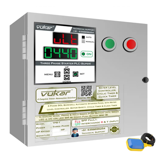
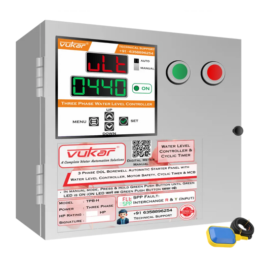
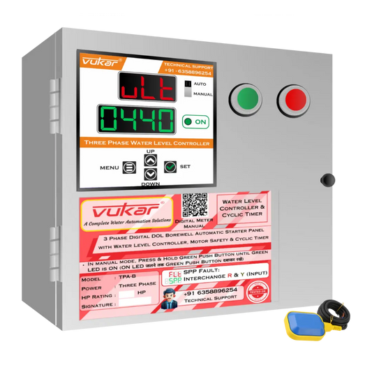
For a sump-to-overhead-tank system, use a level check at each tank: one stops filling when the overhead tank is full, and the other stops or blocks pumping when the sump is too low. In VUKAR's standard single- and double-float controller range, that two-location job uses the double-float arrangement.
In VUKAR's standard water-level controller range, the single-float arrangement is for overhead-tank control. The double-float arrangement adds the sump or underground-tank check. Here, “double” refers to two tank locations; float-count labels on other systems may mean something else.
Give each tank a clear job
The overhead-tank signal asks for a refill when the water is low and stops it at the chosen full level. The sump signal allows that refill only while the source has usable water.
Think of a low roof tank and an almost empty sump. The roof tank needs water, but starting the pump does not create water in the source. The source-level stop must take priority.
| Overhead tank | Sump | Basic level-control decision |
|---|---|---|
| Needs a refill | Enough water available | Allow pumping, subject to all other control and protection rules. |
| Full | Enough water available | Stop pumping. |
| Needs a refill | Below its safe pumping level | Stop the pump or block its start. |
| Full | Below its safe pumping level | Keep the pump stopped. |
This table describes the basic water-level logic. A timer, motor fault or restart delay can still prevent a start when both tank levels permit it.
When might one overhead-tank float suit the job?
A borewell-to-roof installation may use an overhead float to stop at full level. That float does not measure the borewell's water level. The installation needs its chosen source-water and motor-protection method separately.
A model with one float is therefore not automatically missing a part. It may be intended for a different source and control arrangement. Match the complete system to the site rather than choosing by float count alone.
Two floats do not always mean two tanks
Some designs use separate start and stop floats in one tank. A wide-angle float may instead provide a switching range through its movement. Different control panels use different arrangements.
Do not move a two-float wiring diagram from one system to another. The installer must identify what each input does and which state means “water available” or “tank full.” A float used for filling may need different switching behaviour from one used for emptying.
SJE Rhombus's switch guide distinguishes pump-up and pump-down applications. Follow the instructions supplied with your own switch and controller.
Decide the levels before the electrician installs the floats
Agree where a normal refill should begin, where it should end and how low the sump may safely go for that pump. Allow the float clear movement and keep its switching positions within the usable water range.
Tank access and cable routing also matter. Electrical work should be done with the supply isolated. Do not enter a tank or adjust live sensor wiring to try a different level.
Keep the positions with the system records. A later tank or pipe change should not leave the original float trapped or its stop level above the overflow.
Test the two stop signals separately
Ask the installer to verify the full-tank stop and the low-sump stop using a safe commissioning method. Then confirm the intended restart after the sump refills. That should not require deliberately running the pump dry.
The sump-to-overhead control guide covers the wider transfer task. For the purchase itself, select the phase, pump type and sensor arrangement together.